The Great Experiment
- Louis

- Aug 28, 2022
- 10 min read
Updated: Oct 15, 2022
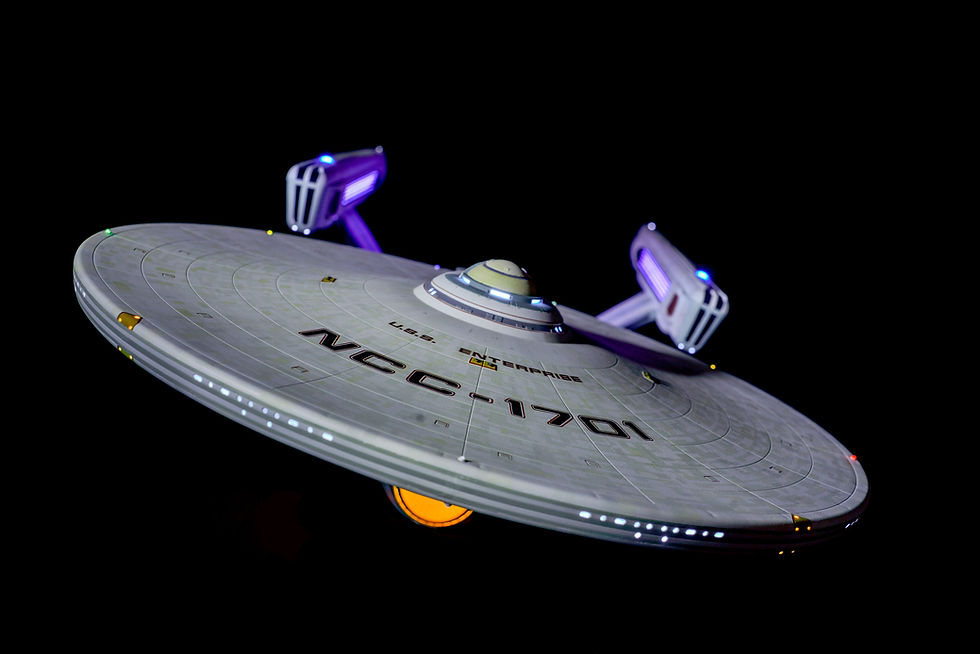
This build was designed to be a replica of the 1979 film "Star Trek The Motion Picture". It also happened to be the most challenging build that I've attempted yet.
This build started out in September of 2020 and finished in July of 2022. This project was to be built as screen accurate as possible, with a full lighting system, sound effects, 3D printed parts and upgrades (FDM and Resin), custom lighting timed to the sounds, HDMI - TV video playback capability, custom "in-scale" imagery (computer screens, consoles, windows, etc.), and app control via iPad. In essence, this was build to be a one of a kind, top of the line, work of art that nobody has seen before....and that's exactly what it became.
I'm no stranger to the 1:350 refit. I've built it before which you can see in on of my older blog posts. I distinctly remember the fitment issues I had with that kit (top of the neck, sensor bands, top of secondary hull, etc.), and I assumed that it would have prepared me for the task ahead. However I had never used a paint masking set before, let alone aztec masking, or this new experimental lighting kit either. Long story short, it was like I was building this kit for the first time. Everything was new. Because of the extensive capabilities within this lighting kit, I had to take a whole new approach to building the Enterprise.

As always I start each build by washing the parts with soap and water. I hand dry them to avoid any residue from the soap. After, I let them sit for 2 hours in a well ventilated room to fully dry. I use the rough side of the sponge when washing, to not only remove the factory mold grease, but to also prep the surface for paint. The roughness of the sponge helps roughen the soft styrene to help primer adhere better.
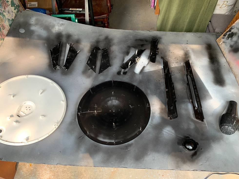
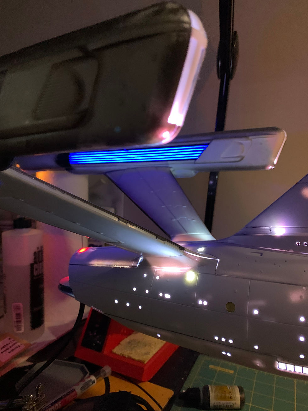
The light blocking is a crucial step (for obvious reasons). Especially with this build having so many lights. The total number of RGB LED's is 421. However this number is technically not correct. Each RGB LED consists of 3 individual LED's to make all the colours (Red, Green, and Blue). Therefore this build actually has approximately 1263 LED's....yeah...I know its a lot.

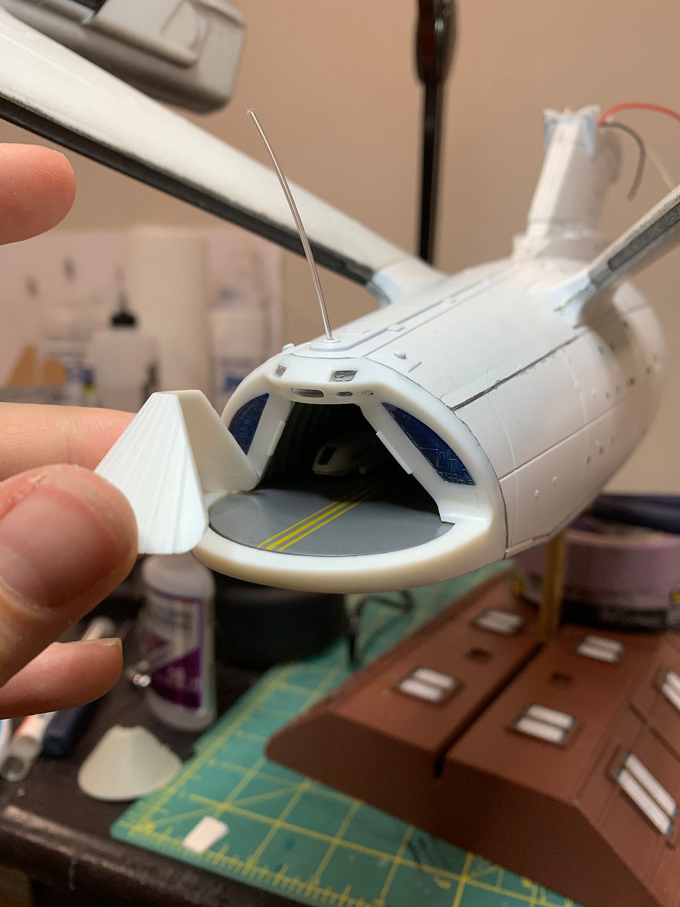
The next step was to get started on the shuttle bay photoetch. With the exterior already primed, it was now time to cut out the lighting slots for the windows. After placing the photoetch on all sides, I dry fit the shuttle bay pieces to see where the major light leak areas were located. Once they were marked, I primed the surface and painted the interior.

Once the walls and floors were painted, I moved onto masking work and decals for the floor. This was a fun task, and the masking set made it very easy. The "Maskdesign" set is made to work with the "Trekmodeler" guide.

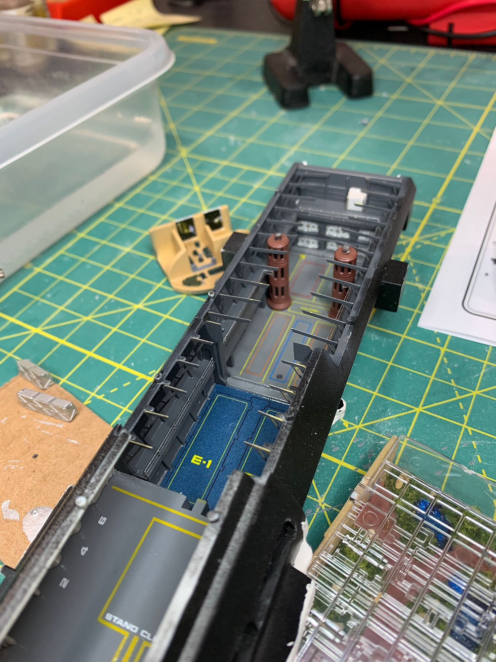
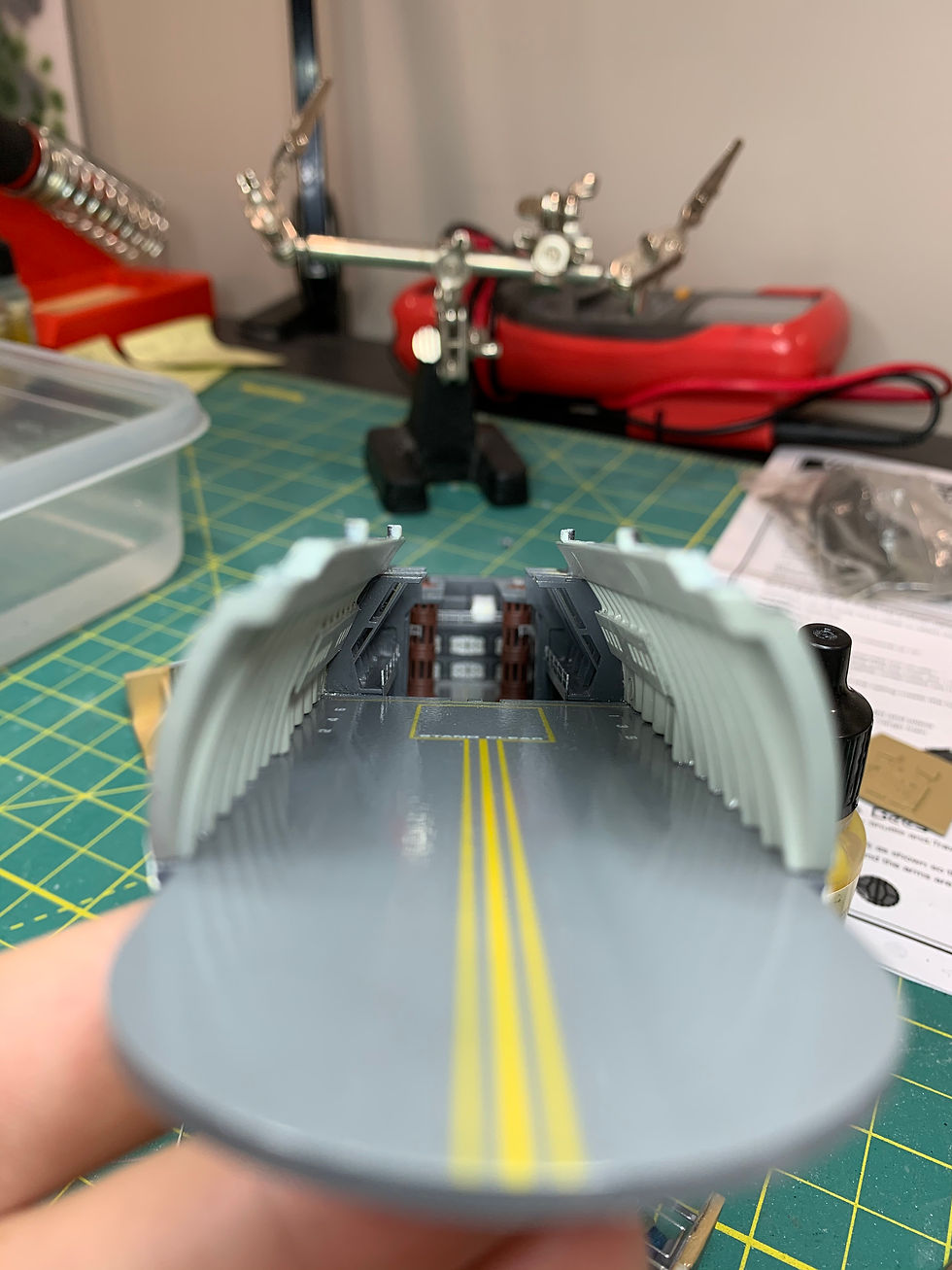
I went with a nice gloss finish for the bay floor. I kept the front walls gloss as well and then the whole rear was matte coated. To me, it gave a showroom floor aesthetic in the front, and a workshop aesthetic in the back.

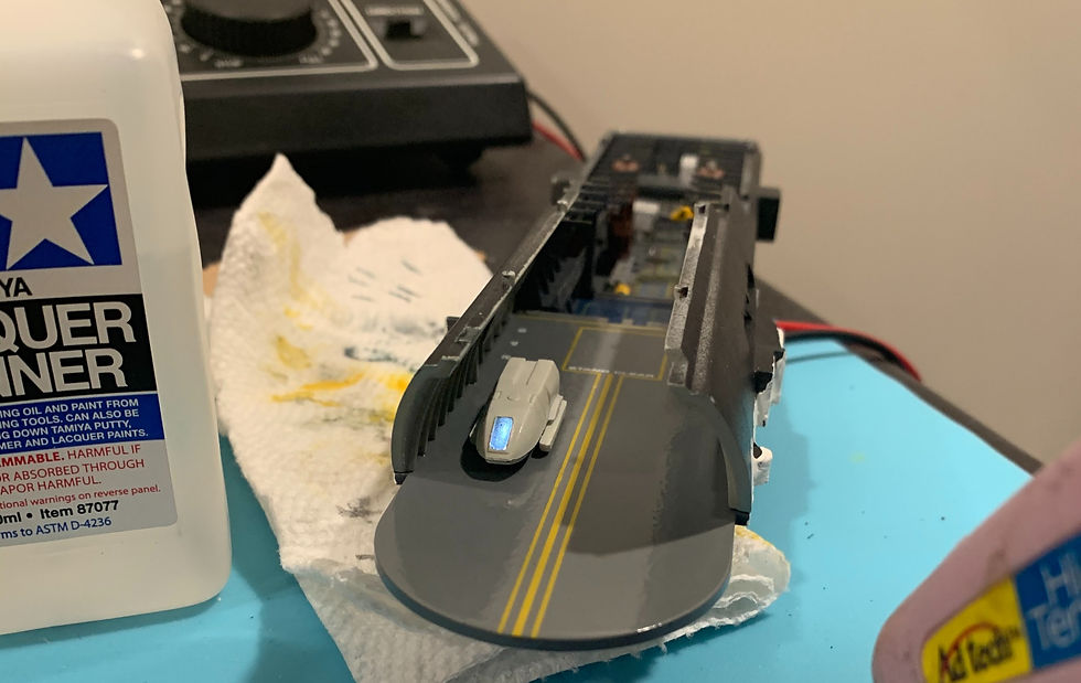
The blurry shuttle in the front was a special project of mine. The customer and I decided that we liked the idea of having an illuminated shuttle in the bay. So I used a dremel and hobby knife to cut out the recessed window. I then placed painters tape in the exposed exterior and dabbed hot glue on the inside to build a translucent window. This took two attempts, because I didn't add enough glue the first time. I also put the rear shuttle door in the "ramp down" position so that the light could illuminate the people standing behind it.

I 3D resin printed the recreation room using free files found online. The quality was really good and the print came out perfect.
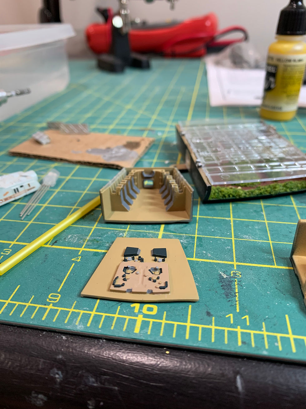

Clearly the sizing of the room is off, the people are in 1:350 scale, but that room is probably at 850-1000 scale. However, this piece was designed for the 1:350 scaled ship...so....forget the scale, it looks awesome!

Next up was the officers lounge. The was a fun task as well because it didn't take very long at all. That why I don't have many photos of the painting process.

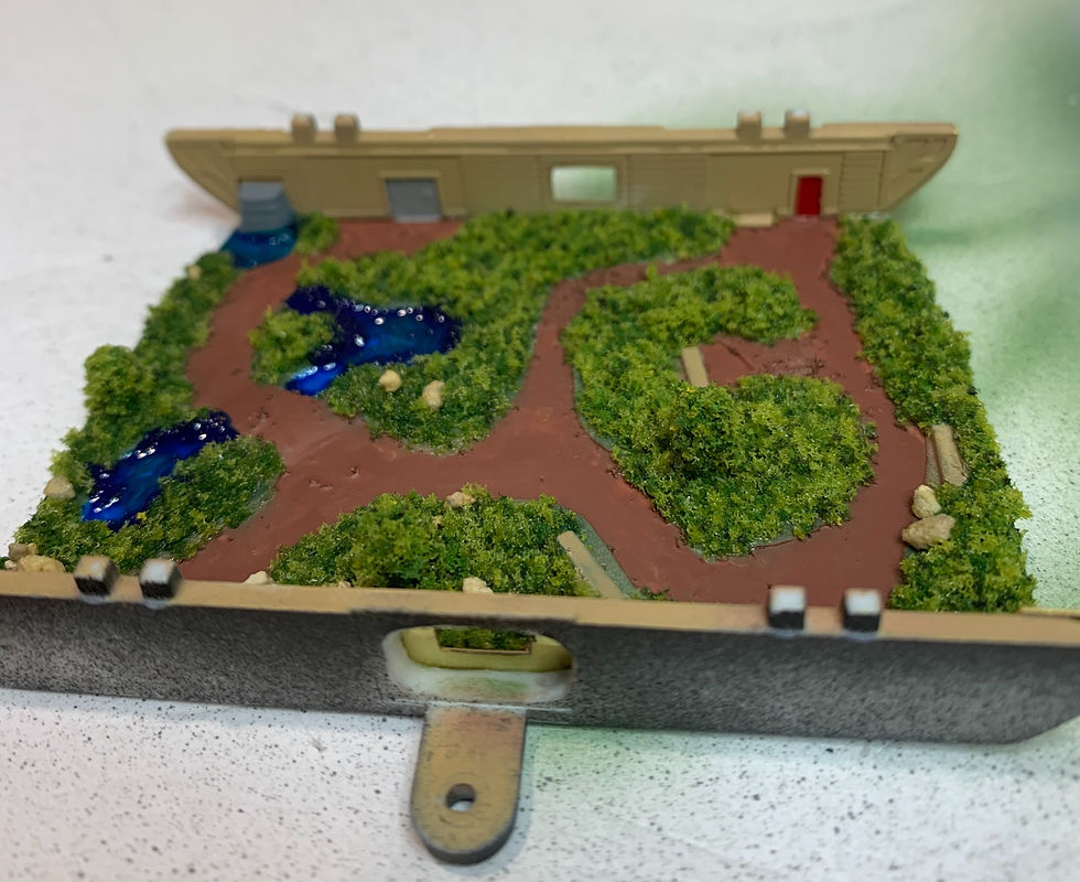
The arboretum was probably one of the most rewarding parts of the model for me. The level of detail that I achieved was exactly what I was looking for. I purchased a "miniatures environment" pack for the grass and rocks. I think it came out perfect.



I did a lot of work on the shuttles this time around, as opposed to the ones I did for my personal build. They were primed, clear coated, decaled, clear coated again, and very slightly weathered.
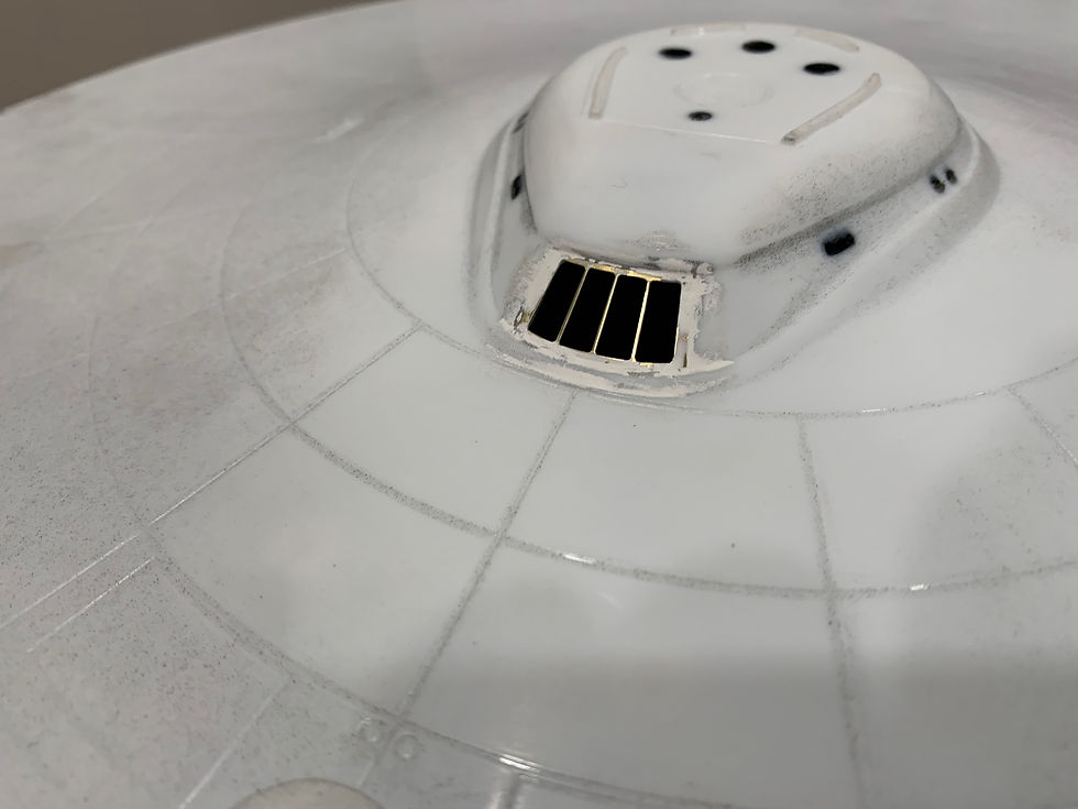
Next up was the photoetch for the officers lounge window and arboretum windows. This was pretty difficult and stressful. The plastic mold is made for the kit window, so you have to cut around the plastic frame to get the desired space. I opted to sand the edges down with a hobby file instead so that it was more controlled than with a hobby knife.



3D printed assets were purchased on Shapeways, from the maker Mark Farinas (Spaceways). For this build, I bought the "TMP bridge interior & exterior", as well as a graphic set (in scale) which was also created by Mark, on Etsy. The detail on these parts are phenomenal, and are well worth the money. The painting required significant magnification, as the bridge was no larger than a plastic water bottle lid...or a dime.

(Above) This photo compares the original kit provided bridge (left) compared to the replacement bridge from shapeways (right). Correct engravings, added detail, higher quality.


Now it was time to work on the secondary hull. This was a daunting task to put it mildly. The lighting kit was my first priority, as it needed to be wired in series. Compared to other lighting kits, most are wired in parallel, and some in series-parallel. The benefits of the parallel circuit, are that you can splice power to separate sections of the build in case there is a short. Think of it like this...you have a Christmas tree set up with lights. Now, with older Christmas lights, when one burns out, all the lights that follow it don't illuminate. This is handy in figuring out which light is burnt, however the rest of the lights will remain off until you add a new bulb to complete the circuit. That is a series circuit. Conversely, with modern lights for trees, when one goes out, the rest remain on. This is because they are all individually hooked up to the main power line. That is parallel. Now imagine what catastrophe would ensue if the lighting was wired (in series) within a completed kit...and one of the first lights burn out...
While the new lighting kit IS hooked up in parallel, in regards to power. It is also hooked up in series, for DATA reasons. Every single LED now has 4 connections...power, ground, DataIn, DataOut. and they MUST be wired in series. This allows the individual control of every LED incorporated within the build. It's very cool what can be created with these LEDs.
Once the photoetch arboretum windows were installed, I worked on installing "strip lighting" along the outside of the shuttle bay. This would help illuminate all the windows on the secondary hull. I also made sure to install the some of the remaining smaller photoetch on the exterior parts.


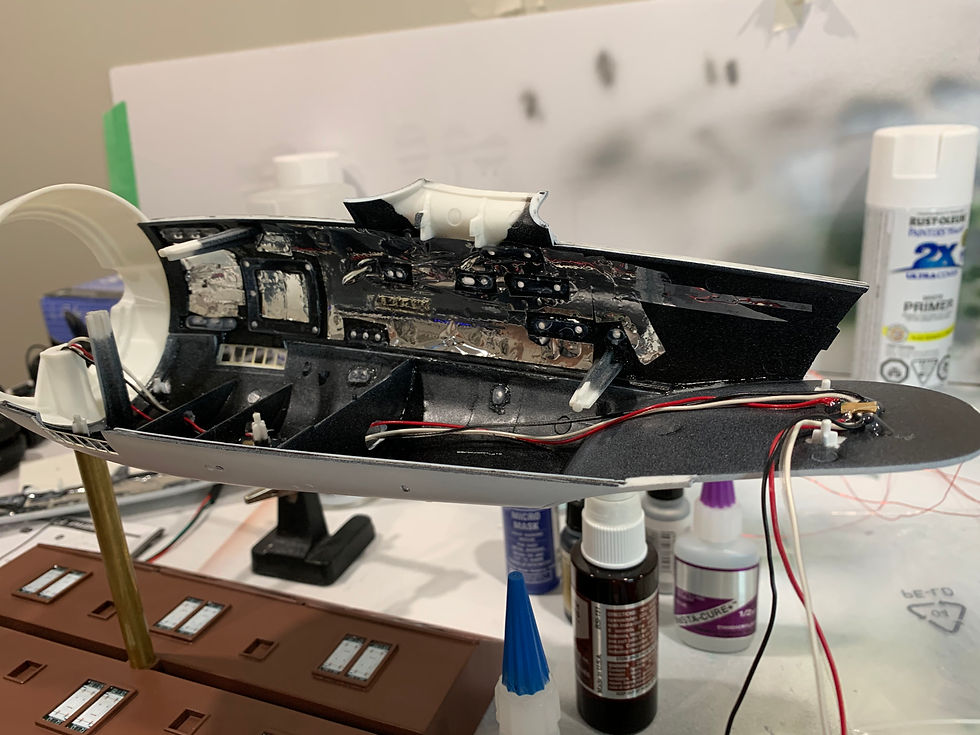


After the arboretum was installed and the shuttle bay along with it, my next step was to work on the neck. It was fairly easy to install lighting, however the seam along the outside front and back, was just as bad as I remembered. It required lots of putty work.
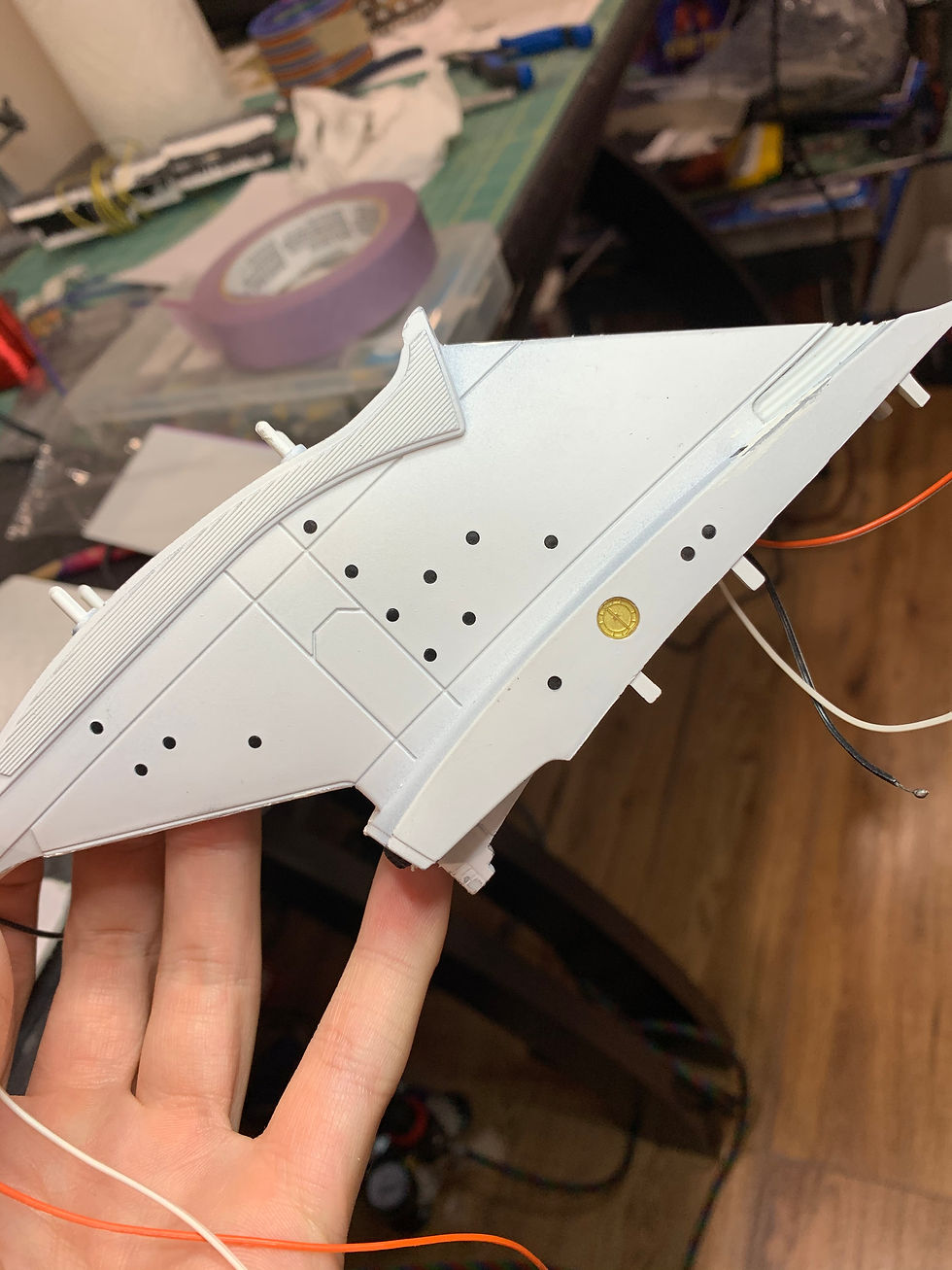
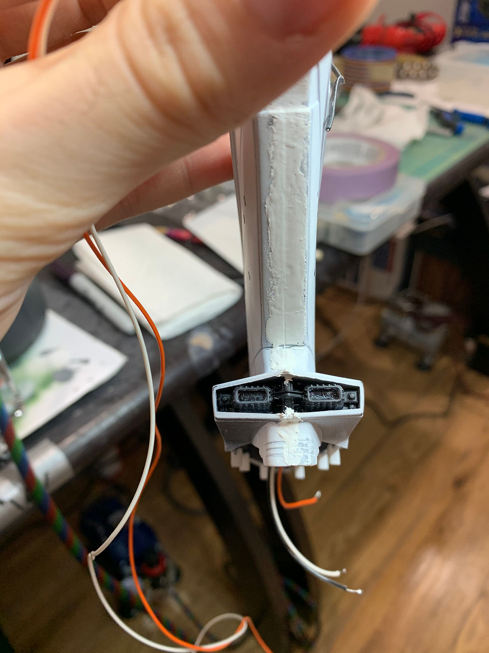
After the neck was completed, I tested the fitment with the secondary hull. It's a fantastic rule of thumb (when building models) to dry fit your parts before cementing them in place. More so with this kit than any other I've built. The fitment, just wasn't good, and it's my second time building this kit.

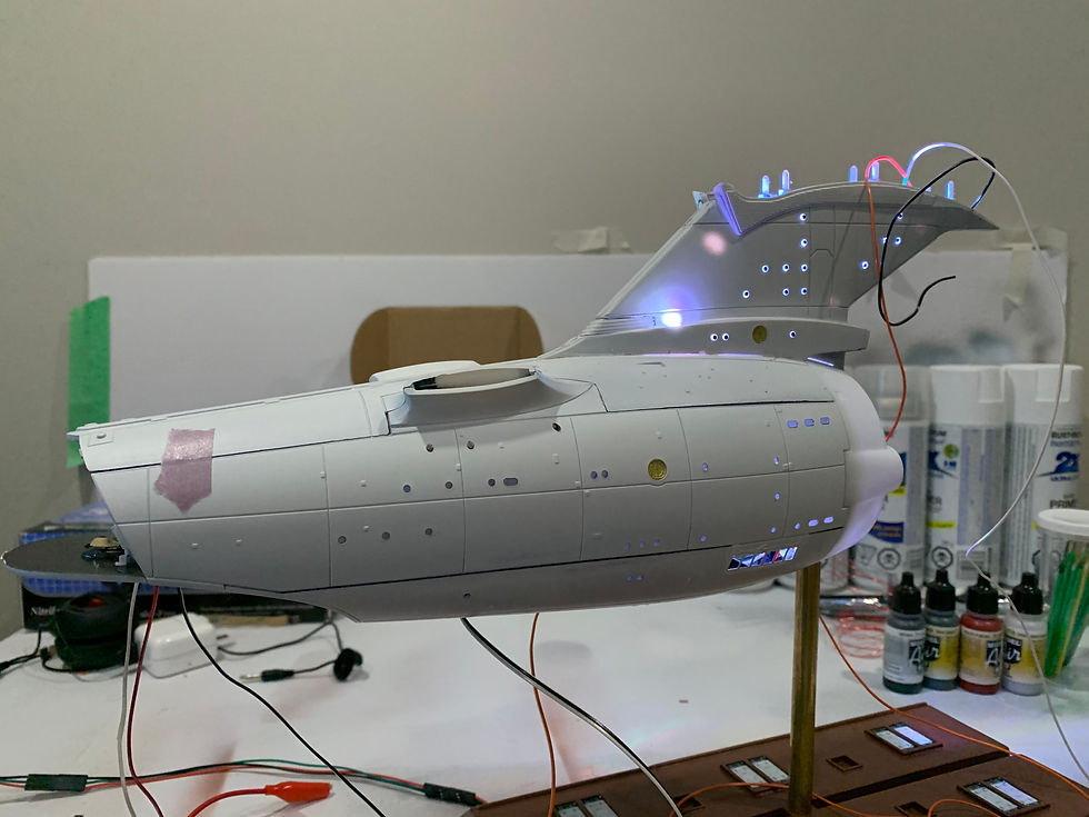
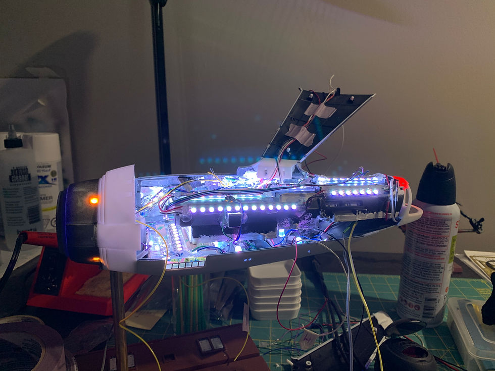
The base was fairly easy at the beginning. Although it would have extensive modifications later on, I still needed something to hold the model up, and theres nothing better than the base itself. The rod was replaced by a brass tube from my local hobby shop (Wheels and Wings).

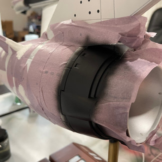
Next up on the agenda were the nacelles. Strip lighting, flood lighting, strobe effects... all parts I had started to become familiar with for this lighting kit. The Scalectronics kit (pro-edition) came with all the necessary lighting required to fully light this kit. However the controller still gave users/builders the opportunity to add their own LED's with a 3.3V power source.
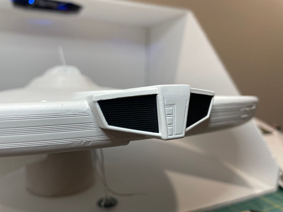
For the "chiller grills" on the nacelle, I decided to use the same method as I previously did, on the old refit. I painted the grills front side, pitch black using "Vallejo Nato Black". Then I would scrape the inside valley's out with a needlepoint hole puncher. The results were exactly what I was looking for...clean and sharp. There were other options to get this result, like the glue method, or the liquid mask method (same thing). However I found that my way resulted in sharper results overall.


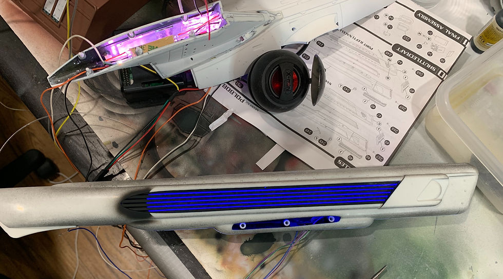
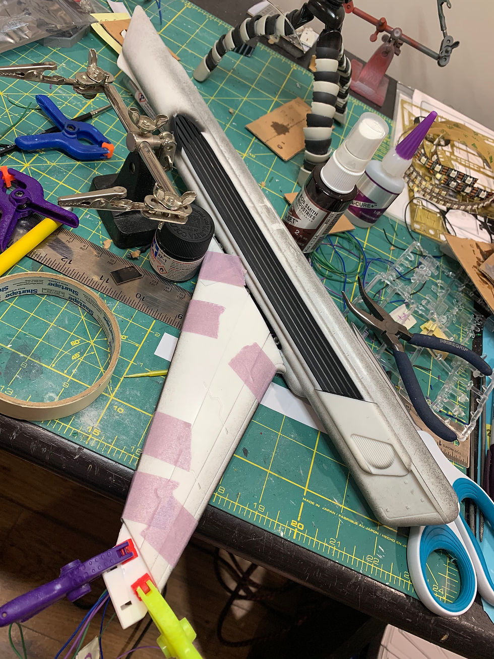
When the lighting was completed for the nacelles, I dry fit them and found an awful step between the two halves...about 2.5-3.5mm in some areas. Lots of putty work was required. My next step was the deflector dish...pretty easy, not a lot of technical stuff to say about that. I thoroughly enjoyed the results of the dish. The clear part was clear/matte coated to give off a frosted effect. The inside of the dish was painted silver to help reflect the amber/blue evenly.


It was time to start assembling the secondary hull. Lesson learned, don't put the nacelles on the kit until they are properly sanded...


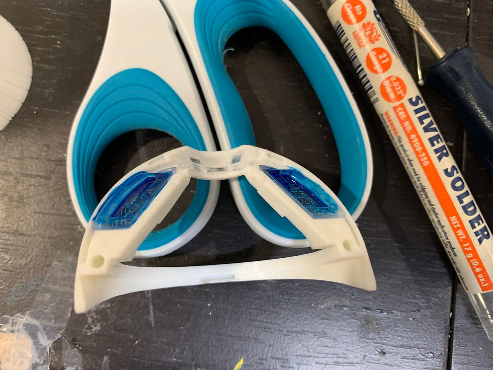

I used string, tape, and a level to get the nacelle angles correct. I also used an absurd amount of "15 minute epoxy" at the base of the pylons to ensure they NEVER come apart. This was due to the pretty bad fitment there as well.
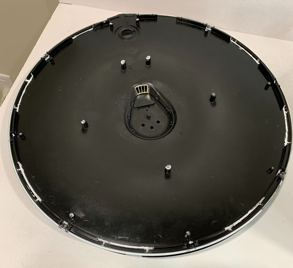
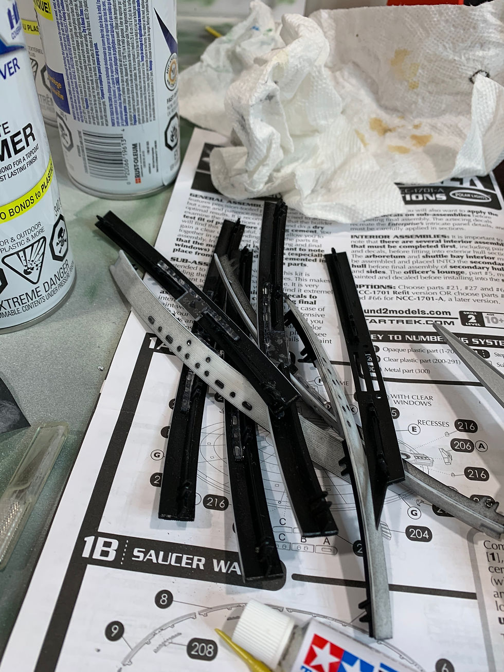
Up next was the saucer. The biggest worry for me, was the lower rim seam. I remember on the first refit that I built, the seam had more of a lip. This was due to me not pushing down hard enough to push the centring pins all the way down. I also had to take into consideration the new 3D printed bridge was going to be already installed at that point, so I had to take care to not damage the new bridge.
I had 3D printed a capsule for the impulse crystal to help with light bleeding through to the windows. It also helped to hold the LED in place. I also printed out a small piece to hold the impulse engine LED's in place, with the same premise as the aforementioned capsule. This saucer held a considerable amount of LED's, but not as many as the secondary hull and neck.
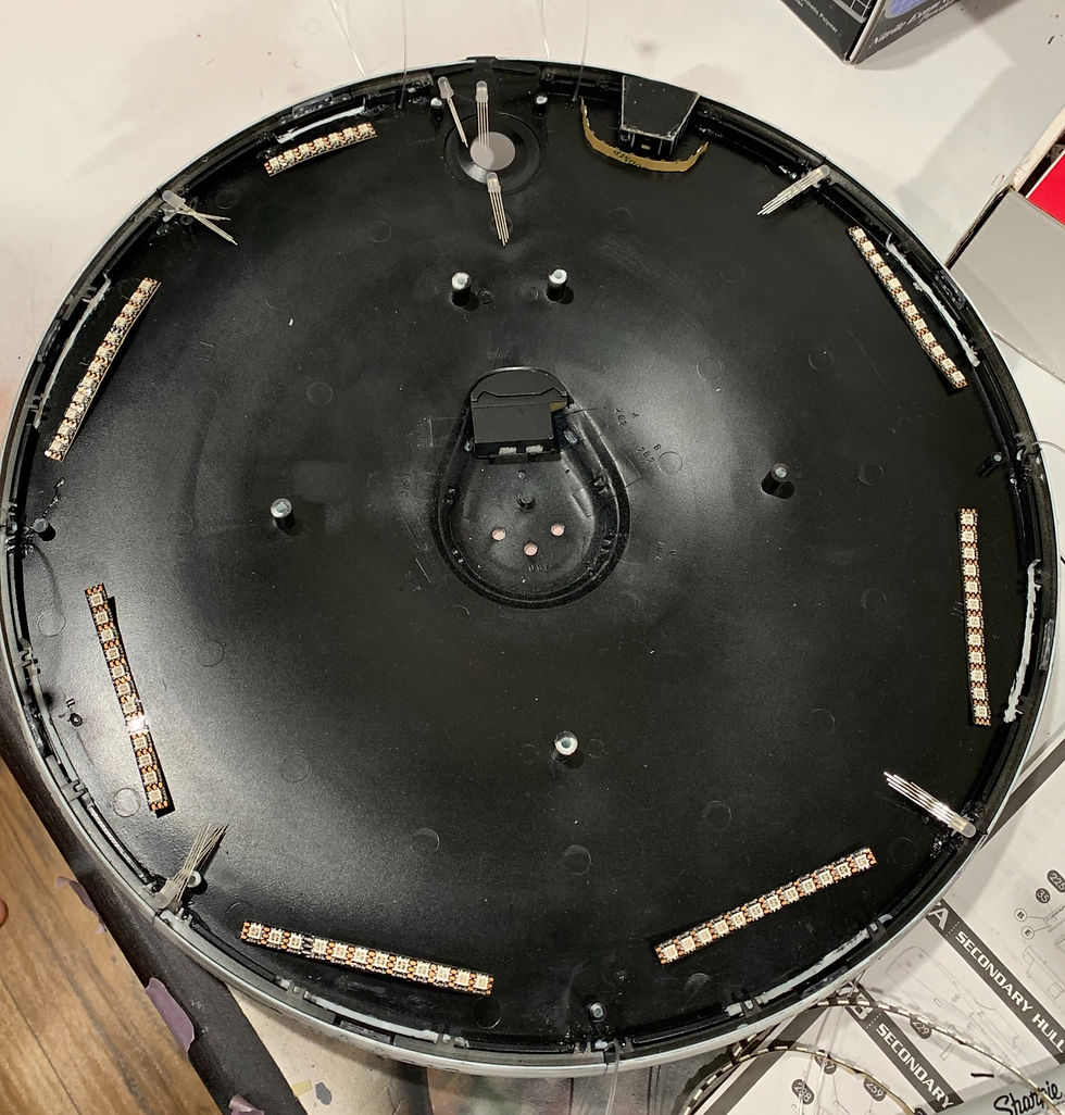

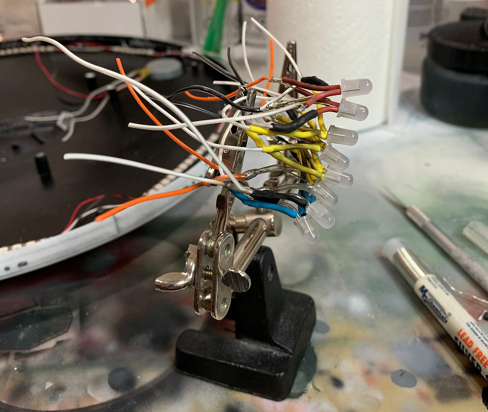
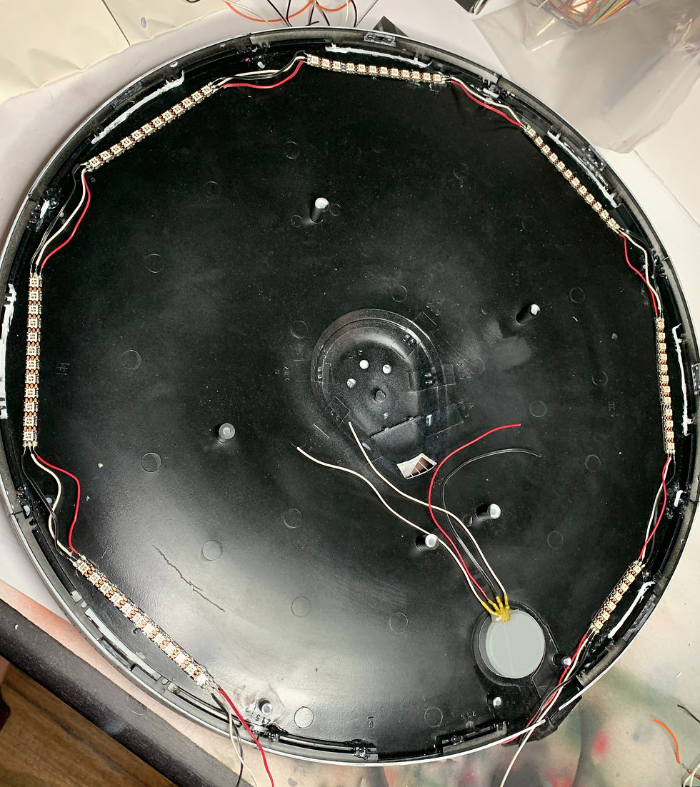
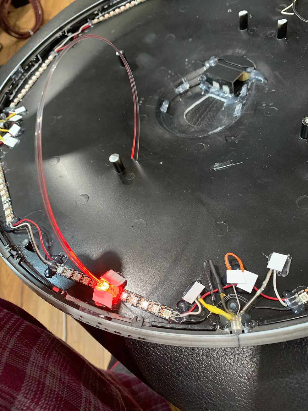
(above) Testing the phaser fibre optics

(above) You can see an image of the Epsilon IX crew member communicating with the Enterprise as his station is being enveloped/assimilated by the V'ger entity. This character was played by actor David Gautreaux. He was originally supposed to play the Vulcan "Xon", a lieutenant on the Phase II Enterprise. It was said that he would replace Spock, due to Leonard Nemoy not reprising the legendary role. We all know how that turned out.

(above) Originally the view screen would have shown this beautiful image of ESD (earth space dock), however the glue that I used reacted very poorly with the image. In the end it had to be removed, and replaced with some Klingon ships from the first movie. That also works out, as this build was to be as accurate to TMP (The Motion Picture) as possible.
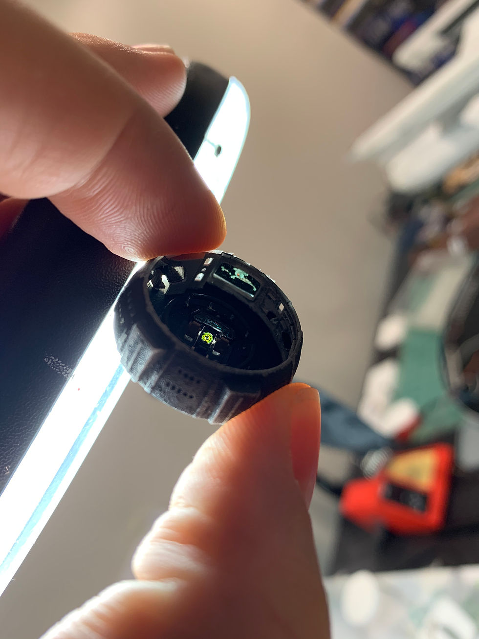

(above) The photoetch window worked out better than I had hoped, much better. My thorough sanding made sure of that. The window "glass" was actually a plastic binder cover sheet. I cut it down to size, and used CA glue to hold it in place. The masking set I purchased, came with masks for the kit supplied windows as well as the photoetch windows. So I was able to paint without fear of blasting my clear inserts with paint.



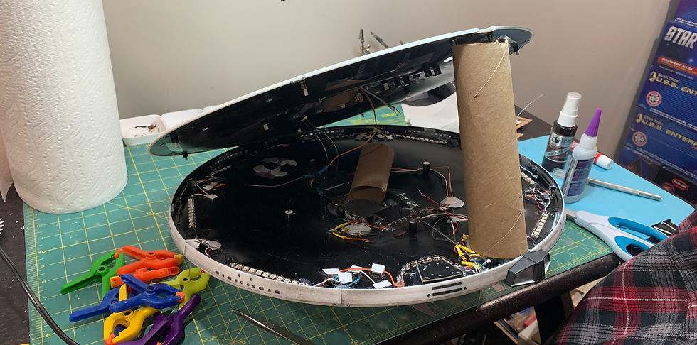


(above) This was a loose fit, to see how it would look. It explains why the ship looks like the front and back are bowing.
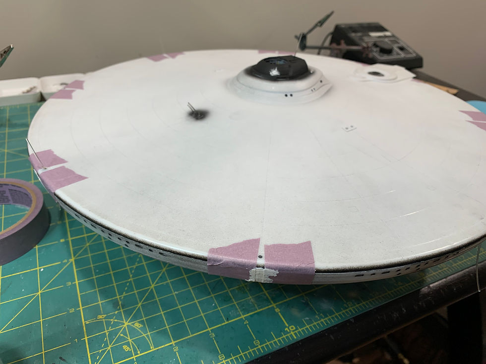
(above) Putty work on the rib seams.

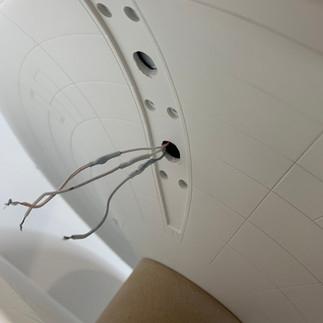
This next section will go into how the lower section of the primary hull came together. The sensor array needed to be hollowed out where it connected to the ship, and the poles that held it in place, needed to be removed with precision. Before any of that took place, I traced the outline of the sensor array so I could put it back exactly where it belonged without any guess work. Then I removed the parts that got in the way, and started with the wiring.

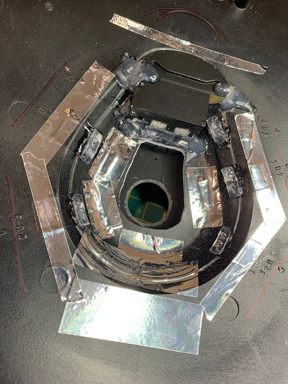
(above) Interestingly, I found that utilizing a spent toilet paper roll, would be helpful to angle the strip lighting. As shown above, you can see a reflection of the strip attached to the toilet roll. This helped cover many other areas that were dimly lit.
Next up were the impulse engines. There were some great photoetch parts for the engines. Both grills being made of brass, helps considerably with light blocking. In the end, it gave of a stellar effect.


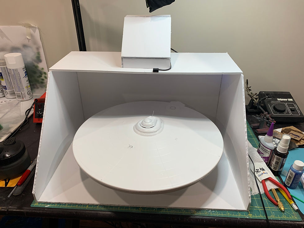
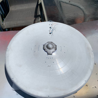
After the saucer was all put together, it was time to paint it with a solid white base coat. After coating 2 times, the ship would be left to sit for 4 days, with proper ventilation. This allowed ample time for the paint to cure and become adequately dry.

Touchup time for some overlooked parts
Secondary hull touchup before second coat.
Light blocking on secondary hull.
Results...
And then the time had come to seal the saucer to the secondary hull. Probably the most daunting task of the whole build. On the previous build, the fitment was horrible, the saucer leaned considerably to one side. Over a 6mm difference between both sides of the neck (on top). SO...my solution was to shave a few of the pins off, leaving 4 (2 in front and 2 in back), and use thin slices of styrene to stack on top of each other to balance the sides. My plan worked perfectly. Once the styrene bits were attached, the neck was flooded with epoxy to ensure an absolute weld between both superstructures. And then I threw the enterprise in the trash...

(above) you can see the neck being solidified by epoxy, with 2 wooden joints being added to help hold it together. You can also see one of the removed pins as well.

(above) This was actually a smart move. Hear me out. With the overabundance of epoxy in the upper neck area, I took a syringe and pumped even MORE epoxy through a small hole under the impulse engine. Propping it up like this, helped the epoxy flow through the whole neck evenly. The results speak for themselves.

Continued in part 2











Connor - You have outdone yourself! You have exceeded all expectations with this build and my expectations were high to start with! This is a beautiful piece of art and having the opportunity to follow along while you were creating the Enterprise was very exciting. I really hope we can do it again.